


Overview
An industrial truck’s steering controller software was upgraded to meet the ISO 13849 safety standard. The team faced major constraints: no existing safety‑compliant process, tight deadlines, and a distributed team with limited experience in the safety-related domain. Starting from a stable baseline, they added a new safety channel while keeping the software continuously releasable. Clear requirements, precise notation, incremental integration, disciplined branching, and continuous testing helped maintain flow and avoid late defects . The team delivered compliant, high‑integrity software within a short timeframe.
Objective
A steering system for an industrial truck needed to be enhanced to meet the requirements of the applicable functional safety standard EN 1175, which references the ISO 13849 standard.
The software for the motor controller and the steering wheel sensor had to be modified to meet the requirements of these standards, and the necessary verification, validation and safety documentation produced.
Factors to be considered
The manufacturer of the steering system motor controller and steering wheel sensor had no previous experience of developing software compliant to functional safety standards, and hence had no processes in place that could be used to achieve this outcome.
Although not developed to comply with functional safety standards, the motor controller and steering wheel sensor products had been developed over a number of years taking safety into account, and the software was very stable. There was not, however, sufficient field data to support a “proven in use” safety argument.
The customer had specific safety requirements, in particular they required a dual-channel architecture but the electronics hardware was not a dual-processor architecture. However, the processor type used was the TMS 570 which is designed for safety-related applications and has dual-lockstep-cores and other safety features such as ECC memory. It was possible, therefore, with careful attention to the design, to satisfy the dual-channel requirement.
Only two members of the team that would be carrying out the work had previous experience with developing safety-related software. The team was also spread across four countries and two continents.
The timescale for making the necessary changes and producing the evidence for safety and compliance to the standard was short.
Approach
The approach was to started with the existing working and reliable software build, a new architecture incorporating a separate safety channel was designed. Safety mechanisms were added incrementally, while maintaining the software functionality in a fully working state throughout.
In the absence of existing company software development processes, it was necessary to create new processes to be followed for the work. This was particularly important in view of the lack of previous experience of many of the team. The processes provided both the formal description of how we would carry out each aspect of the work, but also a basis for training. It was decided to include the specification of all the processes within the software safety plan, including checklists. As ISO 13849 lacks sufficiently detailed requirements in the area of software, the IEC 61508 Part 3 standard was used as guidance.
A set of life-cycles were created around which to structure our work. The purpose of the lifecycles was to provide clarity about how the different activities we were carrying out worked together. They were not used to impose a strict sequence of working. If it made sense to start, and everything was in place for it to be successfully completed, then an activity could start. The safety plan specified the required inputs to each type of activity. A resource-balanced plan was maintained, detailed one month ahead, and less detailed for several months beyond, which described the actual expected sequence and timing of activities.
As the time available to complete the work was short, a way of working had to be established that would produce demonstrably safe software, in the shortest time possible. The common pitfalls of software development had to be avoided: defects discovered late; repeated rework; integration problems; technical debt; a lengthy final “fixing the last bug” phase. Nor was there time to develop the software first and document it afterwards. The software, its design, its verification and the evidence needed to demonstrate its safety had to be produced together.
Speed is not achieved by doing individual tasks faster. It is achieved by eliminating the things that make engineering take longer. Maximum collective effectiveness was the objective, not simply maximum speed of execution of individual tasks. Rather than treating the additional rigour required for safety as additional effort, it was leveraged to reduce defect introduction and bring forward defect removal at every lifecycle stage, avoiding the lengthy debugging phase prior to release often encountered. Emphasis was put on teamwork, motivation, and ensuring that the team had the clarity needed to be able to move fast. The same documentation both helped to provide both clarity during development and evidence supporting the safety claim.
The process
Top-level lifecycle
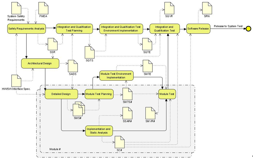
The top-level development lifecycle used is shown in the diagram above. It is based on a V-lifecyle, which is what safety standards recommend. However, it also incorporates iterative development and continuous integration.
Safety requirements analysis
At the start of the project, the system level safety requirements were known, but not clearly specified. The safety requirements analysis phase therefore concentrated on creating a clear and comprehensive specification of the safety requirements at the software level. Initially we tried to do this in Jira, but this proved too slow. We therefore fell back on the option of requirements in tabular format in a Word document.
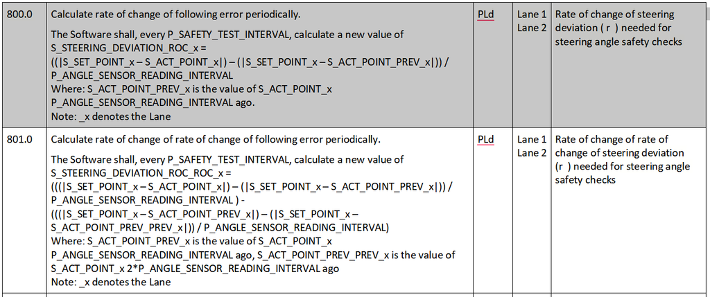
Requirements were specified using mathematical notation, and other unambiguous notations such as state diagrams and state tables, wherever possible. The aim was to provide maximum clarity for the rest of the development work. Requirements expressed in these notations translate more easily to software and avoid the problems inherent in natural language, such as vagueness and ambiguity.
Architectural design
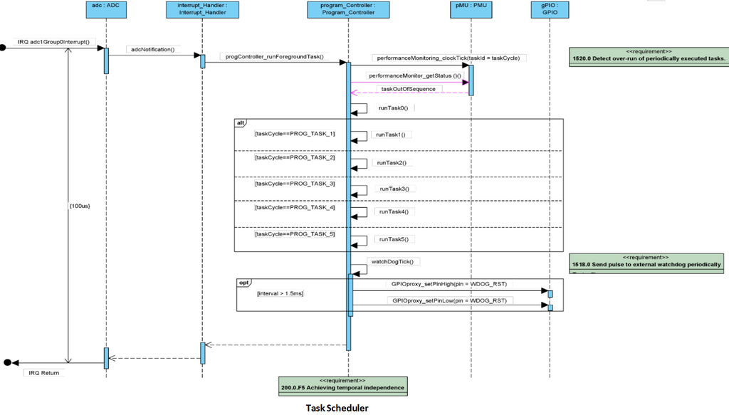
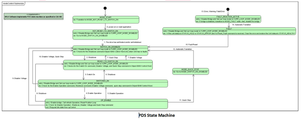
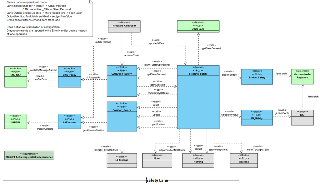
Although the existing software was structured according to a documented layered structure, this fell short of what is needed for safety-related software so an architectural design was modeled using SysML (Visual Paradigm). SysML block diagrams were used to describe static structure, and state and sequence diagrams to describe dynamic behavior. Some examples are show below.
The architectural design was developed in two phases. The first phase was to model the existing architecture. Additional elements were then added to implement the safety functionality. The resulting architecture had two clearly separated sets of modules, one with the main functionality, and the other providing a safety checking channel.
The real-time architecture was a deterministic execution loop, triggered off a single interrupt. Once a module started to execute, it executed to completion. This meant that interference from the safety to the non-safety modules was limited. Safety requirements were added to check for execution overruns, check for over-writing of static data, and to specify the use of separate hardware peripherals for safety and non-safety channels.
Module test environment implementation
This activity was included in the lifecycle to allow for the possibility of having to write a custom test harness. However, it was decided to use an off-the-shelf tool, Tessy, for module testing.
Integration and qualification test planning
Test planning was executed in parallel with the development of the requirements and architectural design. As designing tests provides a useful validation of the clarity requirements and design description, test planning was started as soon as possible. An important objective for this activity was to have tests ready covering an area of requirements before the software modules implementing those requirements were ready for integration. The need was not to allow a backlog to build up of completed modules waiting to be integration and qualification tested.
Integration and qualification test environment implementation
Testing of safety requirements for embedded software often requires specialized testing tools and systems to be available. So development of these was made an explicit activity in the life-cycle. The need was to avoid ever having a completed module being ready for integration, but the testing environment not being ready to test it.
Integration and qualification test
Incremental integration and test was a key part of our approach. We were fortunate enough to start with a very stable baseline. As each module was completed, we added it to our build, and ran all the applicable integration and qualification tests. It is worth noting that we didn’t automate building and unit testing. We would have liked to, but at some point before we started someone had broken the Jenkins set up, and we were so pressed for time that we didn’t prioritize fixing it. Actually we didn’t miss it that much, which I know is heresy!
It is important to note that modules were not thrown into the baseline straight away once module testing was complete. The engineers would first pull the latest baseline onto their branch and then run integration testing to verify that their code actually worked as expected when integrated, and did not break anything. Depending on the nature of the module, test instrumentation was added to the code, to allow examination of key internal variables, and to inject fault conditions. Never degrading the integrity of the master branch was one of the main keys to being able to deliver fast.
The software was configurable using separately downloadable data. We took advantage of this to assist integration of new safety modules, by adding flags in our data to enable/disable safety functions (akin to feature-flags). This meant that we did not have to wait until all modules needed for a safety function were complete before starting integration. However, we did not use this capability to integrate incompletely verified modules into the master branch.
Software release
Software was released whenever it was needed, either for system test or for customer testing. As we always had a fully tested build available, this could be easily achieved. Each release was accompanied by a release note. Due to our strict maintenance of a system in which every change to software was associated with a Jira tasks, and those tasks linked to Git branches in a 1 to 1 relationship, we could generate the release notes very quickly.
Module lifecycle
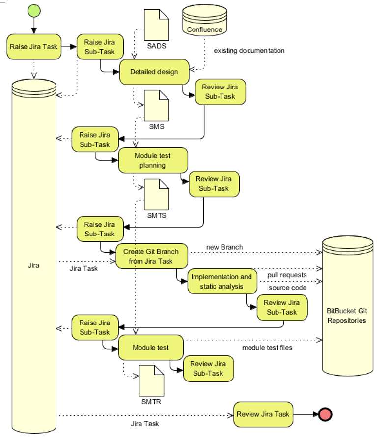
The part in the grey box of the top-level lifecycle is the module lifecycle. This was applied for each new or changed module. So there were multiple instances of this lifecycle running in parallel, each addressing development of a new or changed module. This lifecycle is shown in the diagram below. One point to note is the tight coupling we maintained between our Jira tasks and our Git branches. Every branch was linked to a Jira task, which enabled us to easily trace exactly what was the reason for every change in our code. We were very strict on never making changes on a branch that didn’t directly relate to the linked Jira task. This clarity became invaluable later in the project, when we were still incrementally adding new safety modules, and also making changes to fix bugs found. Writing release notes was also very easy.
Remember that this lifecycle although it is drawn as a set of sequential activates did not impose a strict ordering. In practice, these activities were usually carried out by one engineer who was free to organize their work as they wished.
Detailed design
Detailed design included a detailed specification of the requirements for the module. This provided the clarity that the engineers needed to develop the module quickly and accurately, and to effectively black-box test it.
Importantly, the detailed design also specified the exact interface provided by the module. It also specified the external module interfaces that the module must use for particular purposes, as specified in the architectural design. This gave the clarity that the developers of other modules interdependent with this one needed to work fast and accurately.
The other aspects covered by detailed design were aimed at ensuring that the implementation of the module was easy, by establishing a clear code structure and understanding of states and processing.
Implementation and static analyis
Code was written in MISRA C. All the MISRA rules, both mandatory and recommended, were applied with no global exclusions. Any cases where rules were disabled locally were documented with an individual justification as a comment in the code. Any deviations had to be accepted by the pull request reviewer before the code to be merged into our master branch.
All safety-related software modules were code reviewed as a whole when first written. Thereafter, we used the pull-request mechanism to review changes.
Module test planning
Safety-related software has to be tested thoroughly. Dozens of test cases are needed to fully test each module. This is, perhaps the most unpopular aspect of writing high-integrity code. The Tessy tool was used, which helped to reduce the amount of leg-work, for example by automatically generating test mocks and stubs. It also allowed testing of modules as a whole, executing them multiple times, checking timing as well as functionality. This reduced the number of items needing testing, and more importantly meant that a class of bugs could be discovered at the module testing level that would otherwise not be discoverable until integration.
The test criteria used were complete black-box coverage of the requirements in the detailed design specification, plus all equivalence classes, plus all boundary values. 100% line coverage was required but tests were primarily designed against the requirements, the coverage check was a secondary validation that no code had been included that was not derived from a requirement.
Module test
Module tests for a module were run by the engineer that wrote the code (and in most cases the detailed design and test specification). Module test results were checked as part of the pull request checking. Pull request reviewers also checked that they could build and run the tests.
Results
The goal of delivering software of high-integrity within a very short timescale was achieved with very limited use of special techniques or tools.
The process followed was suitable for software of a moderate safety integrity level. For higher integrity levels, the approach could easily be extended to include use of more rigorous tools for specification and verification, such as SPARK Ada.
Some factors in achieving success were:
- Maintaining a fully viable product throughout, and building on this incrementally without at any point compromising its quality or safety
- Ensuring that activities were not started before all inputs needed for them to be successfully completed were in place
- Flexibility in sequencing and scheduling of activities, while having a clear lifecycle providing clarity about interdependencies between activities
- Developing and verifying each work product in the understanding that it is critical to the success of other activities to which it is an input
- Having a team of good engineers, and letting them perform to their best: not rushing them; letting them concentrate; and giving them autonomy
- Continuous resource-balanced planning to ensure no overloading of engineers and immediate response to changing circumstances
A careful and incremental approach to developing the product, maintaining at every point a fully viable release, was important as it meant that was no backlog of issues to fix late in the project. Note that this was not done by external “governance” or “gating”, but depended entirely on the engineers themselves to achieve this, taking responsibility both for the integrity of the modules that they developed and for their integration into the product.
Rushing to start activities was avoided, care being taken that all the inputs needed were sufficiently complete for the activity to be completed successfully. In this way no backlog of partially completed activities, that were blocked waiting on other tasks, was created.
Although there was a well-defined lifecycle, flexibility was maintained about which activities were carried out when. This helped to keep the team busy, by bringing forward development of modules when they could be started and an engineer was available. For example, there were a number of modules that were not changing, but needed to have proper detailed design and unit test according to the requirements from the safety standard. Work on these could start without waiting on completion of requirements and architectural design.
For each work-product the key question was: “How can this work product provide the maximum benefit to the engineers carrying out activities using this as an input?”. This was important to creating work-products that were not merely produced because a standard or lifecycle says you must have it, but genuinely added value by making the work on other activities easier or more certain.
It is perhaps a cliché to say: “The most important thing was the team”, but nevertheless it is the case that none of this could have been achieved without having engineers that work well both as individuals, and also as a team. It was also important to allow the engineers to perform to their best. This is too large a subject to address here, but three key things are: do not put too much timeline pressure causing engineers to rush; allow engineers to have long periods of intense concentration when working on complex technical work; and give engineers as much autonomy as possible.
Continuous resource-balanced planning is essential for almost any software development project. It is essential to ensure that no engineer is overloaded, and no engineer time is wasted. All activities require input from multiple engineers, so the planning must take this into account. There are also supporting activities that must not be overlooked. With a continuously updated resource-balanced plan in place, it was possible to adjust to circumstances quickly, knowing how this would affect the ongoing and planned activities.